The 25-pair color code, originally known as even-count color code, is a color code used to identify individual conductors in twisted-pair wiring for telecommunications.
Color coding
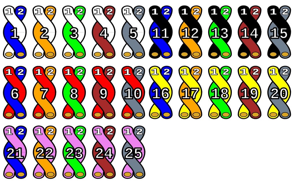
With the development of new generations of telecommunication cables with polyethylene-insulated wire by Bell Laboratories for the Bell System in the 1950, new methods were developed to mark each individual conductor in cables. Each wire was identified by the combination of two colors, one of which is the major color, and the second the minor color. Major and minor colors are chosen from two different groups, resulting in 25 color combinations. The color combinations are applied to the insulation that covers each conductor. Typically, the major color was a solid, background color on the insulation. The minor color was a tracer, consisting of stripes, rings, or dots, applied over the background. The minor color always matches the major color of its paired conductor.
The major, or primary group of colors consists of the sequence of white, red, black, yellow, and violet. The minor, or secondary color was chosen from the sequence blue, orange, green, brown, and slate.
| Pair no. |
Major color | Minor color | ||
|---|---|---|---|---|
| 1 | White | Blue | ||
| 2 | Orange | |||
| 3 | Green | |||
| 4 | Brown | |||
| 5 | Slate | |||
| 6 | Red | Blue | ||
| 7 | Orange | |||
| 8 | Green | |||
| 9 | Brown | |||
| 10 | Slate | |||
| 11 | Black | Blue | ||
| 12 | Orange | |||
| 13 | Green | |||
| 14 | Brown | |||
| 15 | Slate | |||
| 16 | Yellow | Blue | ||
| 17 | Orange | |||
| 18 | Green | |||
| 19 | Brown | |||
| 20 | Slate | |||
| 21 | Violet | Blue | ||
| 22 | Orange | |||
| 23 | Green | |||
| 24 | Brown | |||
| 25 | Slate | |||
The wire pairs are referred to either directly by their color combination, or by the pair number. For example, pair 9 is also called the red-brown pair. In technical tabulations, the colors are often suitably abbreviated.
Violet is the standard name in the telecommunications and electronics industry, but it is sometimes referred to as purple. Similarly, slate is a particular shade of gray. The names of most of the colors were taken from the conventional colors of the rainbow or optical spectrum, and in the electronic color code, which uses the same ten colors (though in a different order).
When used for POTS, the first wire is known as the tip or A-leg (U.K.) conductor and is usually connected to the positive side of a direct current (DC) circuit, while the second wire is known as the ring lead or B-leg (U.K.), and is connected to the negative side of the circuit. Neither of these two sides of the line has a connection to the local ground. This creates a balanced audio circuit with common-mode rejection, also known as a differential pair. The tip and ring convention is based on the 1⁄4″ (6.5 mm) TRS phone connectors, which were employed in telephone switchboards in the 19th and 20th centuries, where the tip contact of the connector is separated from the ring contact by a spacer of insulation. The connection furthest from the cable is known as the tip, the middle connection is the ring, and the (largest) connection closest to the wire is the sleeve.
Larger cables
For cables with over 25 pairs, the first 25 pairs, called a binder group, are marked with mylar ribbons using the colors of the color code starting with a white/blue ribbon, the second binder group with a white/orange ribbon, and so on through the 24th binder group, which has a violet/brown ribbon, and forming a “Super binder” of 600 pairs.
In cables of more than 600 pairs, each of the 100-pair binder groups within the 600 pair of 24 binder groups is wrapped with a mylar binder ribbon, or string, matching the “tip” colors of the color code, starting with white. The pattern then starts over with the first 25 pair group as white/blue, and continues indefinitely, in multiples of 600 pairs or parts thereof. For example, a 900-pair cable will have the first 600 pairs in 24 groups of 25 pairs in a white binder, and the remaining 300 pairs in 12 groups of 25 pairs wrapped in a red binder.
Some cables are “mirrored” or “clocked” with a pattern that is known throughout the telephone industry. Starting with the first binder group in the center, the technician counts the cable’s groups in a spiral direction depending on the location of the Central Office or switch. If looking at the cable’s core and the switch is in that direction, you count the groups counter-clockwise. If the cable is the “field side”, you count the groups clockwise. There are indicators on the mylar ribbons to know where to begin for each layer and a diagram for the different cable sizes should be readily available for reference.
Other color schemes are sometimes used for outdoor cables, particularly outside the U.S., but this color code is common for aerial and underground cables up to several thousand pair in North America. In the UK, the British Post Office (later BT) used this colour code for what is now known loosely as CW1308 spec cables, referring to the Post Office’s “Cable and Wire” specification No. 1308.
Extra pairs and colors
When working on aerial cable splicing and installation, it is common to use a telephone lineman’s set or “Butt Set” to communicate over long distances. To facilitate this, extra pairs of wires are embedded in cables. One extra pair (Red-White) may be embedded into cables that are 6 to 75 pairs; two pairs (Red-White and Black-White) may be encapsulated in cables of 100 to 300 pairs; and three pairs (Red-White, Black-White, and Yellow-White) may be included in cables of 400 to 900 pairs. These extra pairs are often referred to as ‘talk pairs’, and are never used to deliver dial tone.
Optical fiber cables use a twelve-color code, where the first ten are the same as in the 25-pair color code, and the last two are Rose and Aqua.
Memorizing the colors
Various mnemonics have been used to remember the color coding of the major color groups:
“Why Run Backwards, You’ll Vomit”
Source From Wikipedia