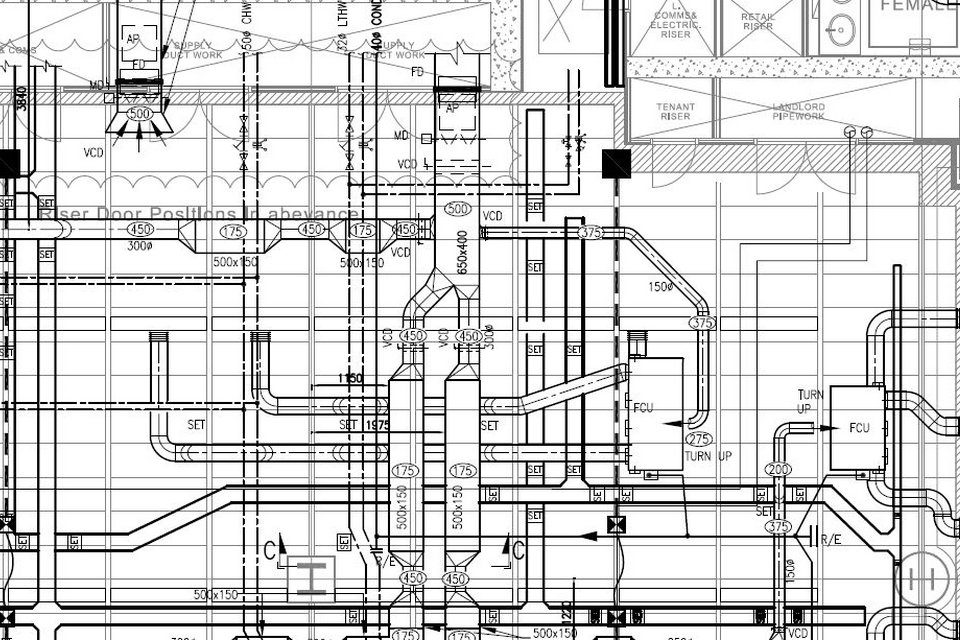
Mechanical systems drawing is a type of technical drawing that shows information about heating, ventilating, and air conditioning. It is a powerful tool that helps analyze complex systems. These drawings are often a set of detailed drawings used for construction projects; it is a requirement for all HVAC work. They are based on the floor and reflected ceiling plans of the architect. After the mechanical drawings are complete, they become part of the construction drawings, which is then used to apply for a building permit. They are also used to determine the price of the project.
Mechanical drawing is the most fundamental in mechanical engineering. In order to accurately communicate the requirements of the designer to the maker, the process of creating the drawings accurately, simply, and clearly according to the specification of the product shape, structure, size, material, processing method, etc. using lines, letters and symbols according to certain rules .
Arrangement drawing:
Arrangement drawings include information about the self-contained units that make up the system: table of parts, fabrication and detail drawing, overall dimension, weight/mass, lifting points, and information needed to construct, test, lift, transport, and install the equipment. These drawings should show at least three different orthographic views and clear details of all the components and how they are assembled.
Assembly drawing:
The assembly drawing typically includes three orthographic views of the system: overall dimensions, weight and mass, identification of all the components, quantities of material, supply details, list of reference drawings, and notes. Assembly drawings detail how certain component parts are assembled.
An assembly drawing shows which order the product is put together, showing all the parts as if they were stretched out. This will help a welder to understand how the product will go together so he get an idea of where the weld is needed. The assembly drawing will contain the following; information overall dimensions, weight and mass, identification of all the components, quantities of material, supply details, list of reference drawings, and notes.
Detail drawing:
In detail drawings, components used to build the mechanical system are described in some detail to show that the designer’s specifications are met: relevant codes, standards, geometry, weight, mass, material, heat treatment requirements, surface texture, size tolerances, and geometric tolerances.
Fabrication drawings:
A fabrication is made up of many different parts. A fabrication drawing has a list of parts that make up the fabrication. In the list, parts are identified (balloons and leader lines) and complex details are included: welding details, material standards, codes, and tolerances, and details about heat/stress treatments. and also
Sketch drawing:
Line diagrams and layouts indicating basic proposals, location of main items of plant, routes of main pipes, air ducts and cable runs in such detail as to illustrate the incorporation of the engineering services within the project as a whole.
Schematic drawing:
The schematic is a line diagram, not necessarily to scale, that describes interconnection of components in a system. The main features of a schematic drawing show:
A two dimensional layout with divisions that show distribution of the system between building levels, or an isometric-style layout that shows distribution of systems across individual floor levels
All functional components that make up the system, i.e., plant items, pumps, fans, valves, strainers, terminals, electrical switchgear, distribution and components
Symbols and line conventions, in accordance with industry standard guidance
Labels for pipe, duct, and cable sizes where not shown elsewhere
Components that have a sensing and control function, and links between them—building management systems, fire alarms and HV controls
Major components, so their whereabouts in specifications and other drawings can be easily determined
Detailed design drawing:
A drawing the intended locations of plant items and service routes in such detail as to indicate the design intent. The main features of detailed design drawings should be as follows:
Plan layouts to a scale of at least 1:100.
Plant areas to a scale of at least 1:50 and accompanied by cross-sections.
The drawing don’t indicate precise positions of services, but should be feasible to install the services within the general routes indicated. It should be possible to produce co-ordination drawings or installation drawings without major re-routing of the services.
Represent pipework by single line layouts.
Represent ductwork by either double or single line layouts as required to ensure that the routes indicated are feasible.
Indicate on the drawing the space available for major service routing in both horizontal and vertical planes.
Installation drawing:
A drawing which based on the detailed drawing, installation drawing or co-ordination drawing (interface drawing) with the primary purpose of defining that information needed by the tradesmen on site to install the works or concurrently work among various engineering assembly. The main features of typical installation drawings are:
Plan layouts to a scale of at least 1:50, accompanied by cross-sections to a scale of at least 1:20 for all congested areas
A spatially coordinated drawing, i.e., show no physical location clashes between the system components
Allowance for inclusion of all supports and fixtures necessary to install the works
Allowance for the service at its widest point for spaces between pipe and duct runs, for insulation, standard fitting dimensions, and joint widths
Installation details provided from shop drawings
Installation working space; space to facilitate commissioning and space to allow on-going operation and maintenance in accordance with the relevant health and safety requirements
Plant and equipment including alternatives and options
Dimensions where services positioning is important enough not to installers
Plant room layouts to a scale of at least 1:20, accompanied by cross-sections and elevations to a scale of at least 1:20
Record (as installed, as-built) drawing:
A drawing showing the building and services installations as installed at the date of practical completion. Generally the record drawing is a development of the installation drawing. The main features of the record drawings should be as follows.
Provide a record of the locations of all the systems and components installed including pumps, fans, valves, strainers, terminals, electrical switchgear, distribution and components.
Use a scale not less than that of the installation drawings.
Have marked on the drawings the positions of access points for operating and maintenance purposes.
The drawings should not be dimensioned unless the inclusion of a dimension is considered necessary for location.
Builder’s work Drawing:
Design stage:
These drawings show the provisions required to accommodate the services that significantly affect the design of the building structure, fabric, and external works. This includes drawings (and schedules) of work the building trade carries out, or that must be cost-estimated at the design stage, e.g., plant bases
Installation stage:
These drawings show requirements for building works necessary to facilitate installing the engineering services (other than where it is appropriate to mark out on site). Information on these drawing includes details of all:
Bases for plant formed in concrete, brickwork or blockwork, to a scale of not less than 1:20
Attendant builders work, holes, chases, etc. for conduits, cables and trunking etc. and any item where access for a function of the installation is required to a scale of not less than 1:100
Purpose made brackets for supporting service or plant/equipment to a scale of not less than 1:50
Accesses into ceilings, ducts, etc. at a scale of not less than 1:50
Special fixings, inserts, brackets, anchors, suspensions, supports etc. at a scale of not less than 1:20
Sleeves, puddle flanges, access chambers at a scale not less than 1:20
Details to include:
Size, type, and layout of ducting
Diffusers, heat registers, return air grilles, dampers
Turning vanes, ductwork insulation
HVAC unit
Thermostats
Electrical, water, and/or gas connections
Ventilation
Exhaust fans
Symbol legend, general notes and specific key notes
Heating and/or cooling load summary
Connection to existing systems
Demolition of part or all of existing systems
Smoke detector and firestat re-ducting
Thermostat programming
Heat loss and heat gain calculations
Special condition
The American Design Drafting Association (ADDA) has developed a Drafter Certification Test. The test assesses the drafter’s skill in basic drafting concepts: geometric construction, working drawings, and architectural terms and standards. The test is administered periodically at ADDA-authorized sites.
Mechanical system drawings must abide by all of the following regulations: the National Building Code of Canada, the National Fire Code, and Model National Energy Code of Canada for Buildings. For residential projects, The National Housing Code of Canada and the Model National Energy Code of Canada for Houses must also be followed. These drawings must also adhere to local and provincial codes and bylaws.